The GTOCP3 Control Box contains all of the circuitry to drive the two servo motors and the logic required to circumnavigate the sky. It functions as "the brains" of your mount translating the commands that are received from external software (Keypad, planetarium program or other software) into electrical signals to the motors to produce movement and other critical functions. It also makes all the required calculations and determines the safe and proper path for GoTO slews.
The main function of the GTO Control Box is
to drive the R.A. and Dec. motors, which are DC
servos with built-in shaft encoders. The rotation
rate and precise number of rotations of each motor is controlled
with a servo feedback loop. The servo looks at the return
pulses from the shaft encoders and adjusts the
current to the motor so that the rate is identical
to the commanded rate (i.e. from .25x sidereal
to 1200x sidereal). The precise number of motor rotations is translated
into incredibly accurate R.A. and/or Dec. distances.
The servo is digitally
controlled, and the shaft position is updated at a rate of 2000 times
per second.
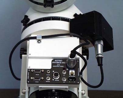
This electronics box is mounted directly on the R.A. axis of the 1200 and 900 mounts (as shown in the photo), on the side plate of the 1600 and 3600 and is a stand-alone unit for the Mach1, 1100, 400 and 600E mounts. The freestanding unit attaches to your pier or tripod with the handle on the fabric pouch or the Control Box Adapter (CBAPT) both included with the Mach1GTO.
The GTOCP3 shipped with the Mach1GTO mount is completely black-anodized to match the mount. The control boxes shipped with the 900GTO, 1100GTO, 1200GTO, 1600GTO and 3600GTO mounts have a black-anodized panel where the connectors are located and the remainder of the box is painted the same cream-white as the mounts.
The command language protocol that is programmed into the microcontroller of the GTOCP3 Control box allows the sophisticated control functions of your mount. Please keep in mind that the software that communicates with the mount will determine which commands are utilized. For instance, although the control box is programmed to include a command that can implement a timed guide move, if the software does not issue the command, this feature cannot be used.
For optimum utilization of the advanced functions in the command language protocol, we recommend that you control your mount with either the GTO Keypad, software that utilizes the ASCOM V2 driver or the Astro-Physics Command Center (APCC). All of these control options were written by Astro-Physics. For more information, see: Control Your GTO Mounts with Your Keypad, Computer or Mobile Smart Devices.
Here are some of the key features and functions available in the latest versions of the GTOCP3 Control Box:
- Allows Automatic "Deadman Switch" Safety Timer function. This feature confirms that mount is communicating with the PC and COMs are functioning properly. If not, the mount will park at the end of a user-defined countdown preventing pier crash. This important safety feature is implemented in both APCC Standard and Pro Versions.
- Reads capability of PEM state, guide, center and slew rates and of drift (both axes) and trim (both axes). This feature is implemented through polled status command in the ASCOM V2 driver and APCC Standard and Pro Versions..
- Allows Auto-Park. This will cause the mount to enter a parked state whenever power is removed and this state is remembered through power cycles. When the command is invoked, default sidereal rotation will NOT start up the moment that power is applied. This will be the recommended setting for any remote observer/imagers. This does NOT try to move the mount into a pre-defined park position.It simply puts it into a parked state when power is removed. This feature is the default in APCC Standard and Pro Versions..
- Improved Meridian Swap logic. The new logic is more streamlined and robust. It is applied to all go-to slew input - Keypad and computer programs.
- Accepts timed guide move command. This allows control programs to introduce precise motion without the complication of providing accurate time separation between the move and quit commands.
- Allows variable tracking rate commands in both RA and Dec axes. These are useful for tracking objects that are not fixed relative to background stars, like comets, asteroids, satellites and the Moon.
- Accepts variable centering rate commands in addition to the commanded rates of 0.25x, 0.5x, 1x, 12x and 64x.
- PEM - Periodic Error Memory correction - make your correction just once, remains in memory permanently.
- PEM memory command. PEM memory is accessible to external software programs in order to smooth out and modify the curve. PEMPro by Ray Gralak and distributed by CCDWare supports directly reading from/writing to the PE storage locations. This allows more accurate programming of the mount's PEM (that is, the mount does not have to interpret move or autoguider commands). Also, programming is significantly quicker than waiting for one worm cycle's worth of playback (5.6 to 7.5 min, depending on the mount model) as is the case for the GTOCP2. Also, PEMPro reads parameters and calculates the mount's worm period (useful if you have a non-Astro-Physics mount with the GTO Control System.
- Query to mount regarding the position of telescope on east or west side of the pier/tripod. This command is useful for dome control software and remote control.
- High-precision mode assures accuracy of R.A. format to tenths of seconds in R.A. (1.5 arc seconds)
- Servo control can be commanded using Alt-Azimuth coordinates.
- Park command de-energizes motor and remembers R.A./Dec. coordinates when power is removed. Restores saved R.A./Dec. coordinates on next power up and calibrates to them when commanded. When the power and keypad are restored, the mount will stay parked and not resume tracking until the Resume from Park function has been entered on the keypad.
- Allows recalibration even when scope has crossed the meridian and is on the wrong side of the mount.
- If motor stalls more than 1 second, the drive will shut off. This is a safety feature to prevent motor burnout in case of severe load on the motor due to an extreme imbalance condition or if the power to the mount has been accidentally left on and the scope has hit a hard stop.
- Automatic meridian swapping in GoTo slewing mode.
- Continues to track at sidereal rate, even while slewing so that your position is always accurate.
- Allows E-W reversal in R.A. and N-S reversal in declination for correct object orientation and movement in eyepiece.
- Allows R.A. and declination backlash control.
- Functionality to support GTOELS and GTOAE control boxes, which are used with the Precision and Absolute Encoder options.
- Provides full functionality of the AP V2 ASCOM Driver and APCC through at least February 2016. Provides all the commands required for all functions of the AP V2 ASCOM driver (available free of charge) and our Astro-Physics Command Center (APCC) software (optional purchase).
- Machined aluminum housing provides robust protection for electronics.
- All input lines are protected against heavy static discharge with transorbs. Larger internal chip to allow additional functions. FCC and CE certified. Lead-free electronics.
- Two threaded drainage holes are drilled into the lower part of the control box housing so that excess moisture can drain easily. This may prove useful if you live in an area with high humidity.
- Dovetail construction allows quick removal from Mach1GTO, 900, 1100, 1200, 1600 and 3600 mounts.
- Removeable microprocessor chip allows upgrades in future.
- 12V connector for locking power cable.
- Autoguider connector for any CCD with modular RJ-11-6 connector.
- Two 9-pin RS-232 serial ports (DB9 female connectors, a.k.a. DE9) so that user can use two programs, for instance PulseGuide and a planetarium program, simultaneously, if desired. The user must have two COM ports available on their personal computer to use the software together.
- Focus connector - for 3.5mm phono plug (JMI, Meade or other DC synchronous electric focusing motors only).
- Reticle connector - for guiding eyepiece with an illuminated reticle that has a 3.5mm phono plug or the cable for our own PASILL3, PASILL4 and PASILL4L (versions of Polar Alignment Scopes).
- 6-V 200mA output accepts 3.5mm phono plugs to power Pentax 6x7 camera directly from the mount.
- Northern and Southern Hemisphere switch.
- GTO Keypad Controller locking connector.