Guidelines for Using 6" Trays and the Pier/Tripod Control Box Adapter

These guidelines offer suggestions for getting the most from your pier or tripod. Click on these links if you need information regarding each pier or tripod.
We invite you to refer to the information contained in the tables below to help you decide which arrangement will be most suitable for your particular situation
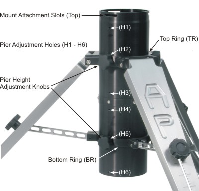
To aid in understanding the tables, please use the picture at right to identify the appropriate mounting holes for the Pier/Tripod Control Box Adapter.
Check out our page with example photographs!
Please note the following:
Select the pier or tripod that you plan to use:
Berlebach Planet Tripod (AWTBER2) and Adjustable Wood Tripod (AWT000, no longer available)
In general, these accessories are attached to the adapter at the top of the tripod by replacing one of the pier knobs with a bolt that is provided with the accessory. Tripods sold after May 2007 were equipped with the six-hole Tripod Adapter (ADATRI). Earlier tripods have 3 holes. Please refer to the notes at the top of this page.
Important Note: The Berlebach Tripod requires the use of the 8" Extension for 6" Eagle Pier (EAGLE6E8) when using trays.
| Single Level Support Bar (TRAYSB1) and Tray (TRAY06) or (TRAY06H) | Appropriate Fasteners | Control Box Adapter (CBAPT) see hole position reference |
Appropriate Fasteners | Bi-Level Support Bar (TRAYSB) | |
|---|---|---|---|---|---|
400 |
* One, two or three Single-Level Support Bars and tray(s). * Fasten on any side of the mount. (However, at lower latitudes, the counterweight may interfere with the tray(s) on the north side - especially with 400 mounts.) |
1/4x1" FH |
* The Berlebach Tripod requires the Q6280KIT, which will extend the CBAPT beyond the locking levers located at the top of the legs. * Attach on south side of the mount so cables can be routed most effectively. * Attach the adapter using the angled tab (4) so that the bracket clears the legs (preferred). This method will work regardless of the tripod's leg orientation. * The bracket can also be mounted from the top hole (1) when the pier knobs are positioned between the legs although it will bind slightly against the leg hardware. This position provides the smallest profile. Hole (1) cannot be used if your mount is positioned with the pier knobs directly above the legs. |
1/4x1" FH |
N/A |
6" x 24" Portable Pier (6X24PP)
| Single or Bi-Level Level Support Bar (TRAYSB1 or TRAYSB) and Tray (TRAY06) or (TRAY06H) | Appropriate Fasteners | Control Box Adapter (CBAPT) see hole position reference |
Appropriate Fasteners | |
|---|---|---|---|---|
|
400 |
The support bars and accessory trays cannot be used with this pier. |
N/A |
Can be used with Q6280KIT to extend CBAPT beyond the top bolt. |
N/A |
6" x 42" Portable Pier (6X42PP)
For the A-P Portable Pier, the accessories generally attach at the top of the pier. In some situations, it will be necessary to substitute one of the pier knobs with a bolt that is provided with the accessory.
| Single Level Support Bar (TRAYSB1) and Tray (TRAY06) or (TRAY06H) | Bi-Level Support Bar (TRAYSB) and Tray (TRAY06) or (TRAY06H) | Control Box Adapter (CBAPT) see hole position reference |
Appropriate Fasteners | |
|---|---|---|---|---|
|
400 |
* Current piers: The Accessory Trays can
be used. It is possible to attach up to 3 support bars (either style) and
up to 6 Accessory Trays. Fasten support Bars using nuts and
washers on the inside of the pier. The Support Bars can
be left in place for transport. * Older piers: Do not have extra holes already drilled for this purpose. Owners can modify their pier to accept support bars and trays by drilling holes a minimum of 8.5" down from the top of the pier so the tray will clear the struts. |
* Attach on south side of the mount so cables can be routed most effectively. * Attach the adapter using the angled tab (4) so that the bracket clears the eyebolt below it. |
Knob or 1/4x3/4" FH |
|
6" x 32", 48", 54" or 62" Portable Pier (6X32PP), (6X48PP), (6X54PP), (6X62PP)
For the A-P Portable Pier, the accessories generally attach at the top of the pier. In some situations, it will be necessary to substitute one of the pier knobs with a bolt that is provided with the accessory.
| Single Level Support Bar (TRAYSB1) and Tray (TRAY06) or (TRAY06H) | Bi-Level Support Bar (TRAYSB) and Tray (TRAY06) or (TRAY06H) | Appropriate Fasteners | Control Box Adapter (CBAPT) see hole position reference |
Appropriate Fasteners | |
|---|---|---|---|---|---|
|
400 |
* Will work with all of the above size Portable Piers. * One, two or three Single-Level Support Bars with tray(s). * Fasten on any side of the mount. (However, at lower latitudes, the counterweight may interfere with the tray(s) on the north side - especially with 400 mounts. An additional tray can be added on the north side at the bottom of a Bi-Level Support Bar - see next column over.) |
* Will work with all of the above size Portable Piers. * One, two or three Bi-Level Support Bars, each with either style of accessory tray * Fasten on any side of the mount. At lower latitudes, only the lower position may be usable on the north side of the mount. * If the Control Box Adapter is also used, then just two of the Bi-Level Support Bars can be attached. |
Knob or 1/4x3/4" FH |
* Attach on south side of the mount so cables can be routed most effectively. * Mount the adapter with the angled tab down by using the top hole (1) for a tight fit to the tripod (preferred method). * The bracket can also be mounted from the angled tab (4) providing a better view of the control box. That configuration, however, does create more of an obstacle. |
1/4x3/4" FH or Knob if using angled tab (4) |
6" Eagle Adjustable Folding Pier (EAGLE6-EZ)
 The 6" Eagle
Adjustable Folding Pier (EAGLE6-EZ) will be treated a bit differently
than the tripods or Portable Piers outlined above. They all had basically
one attachment point for accessories - the top where the mount is also attached.
Because of its adjustable nature, the 6" Eagle has a variety of potential
mounting points. See the page of
examples! We have no doubt that our clever customers will find more ways
to use these accessories than we could possibly outline here! To avoid confusion,
please review the following information:
The 6" Eagle
Adjustable Folding Pier (EAGLE6-EZ) will be treated a bit differently
than the tripods or Portable Piers outlined above. They all had basically
one attachment point for accessories - the top where the mount is also attached.
Because of its adjustable nature, the 6" Eagle has a variety of potential
mounting points. See the page of
examples! We have no doubt that our clever customers will find more ways
to use these accessories than we could possibly outline here! To avoid confusion,
please review the following information:
Table Notes:
Click the thumbnails below to see examples at each setting, or click here to see the whole page of examples!
| Single Level Support Bar (TRAYSB1) and Tray (TRAY06) or (TRAY06H) | Bi-Level Support Bar (TRAYSB) and Tray (TRAY06) or (TRAY06H) | Appropriate Fasteners | Control Box Adapter (CBAPT) see hole position reference | Appropriate Fasteners | ||||||||||||||||||||||||||||||||||||||||||||
|---|---|---|---|---|---|---|---|---|---|---|---|---|---|---|---|---|---|---|---|---|---|---|---|---|---|---|---|---|---|---|---|---|---|---|---|---|---|---|---|---|---|---|---|---|---|---|---|---|
Lowest |
|
Not Applicable |
|
|
|
|||||||||||||||||||||||||||||||||||||||||||
Middle |
|
Not Applicable |
|
|
|
|||||||||||||||||||||||||||||||||||||||||||
Highest |
|
|
|
|
|
|||||||||||||||||||||||||||||||||||||||||||
8" Extension (EAGLE6E8) click |
* One, two or three Single Level Support Bars, each with either style of accessory tray. * Fasten on any side of the mount. (However, at lower latitudes, the counterweight may interfere with the tray(s) on the north side - especially with 400 mounts.) * Additional trays and support bars can always be added below the extension using the guidelines above. |
* One, two or three Bi-Level Support Bars, each with one or two of either style of accessory tray. * Replace knob joining pier top to 8" Extension with 1/4x5/8" BHW to keep knob from interfering with bottom of support bar. * Fasten on any side of the mount. (However, at lower latitudes, the counterweight may interfere with the top tray(s) on the north side - especially with 400 mounts.) The bottom tray will be fine. |
1/4x1" FH (Replace pier knob(s) on bottom of extension with 1/4x5/8" BHW if using Bi-Level Support Bar) |
* Attach on south side of the mount so cables can be routed most effectively. * Lower attachment points can still be used following the guidelines above. See the note (a) below. |
1/4x1" FH |
This page was last modified: August 29, 2022
Astro-Physics, Inc.
11250 Forest Hills Road, Machesney Park, IL 61115, U.S.A.
Phone: 815-282-1513 Fax: 815-282-9847